| Understanding Functional Safety FIT Base Failure Rate Estimates per IEC 62380 and SN 29500 | 您所在的位置:网站首页 › engineering judgment › Understanding Functional Safety FIT Base Failure Rate Estimates per IEC 62380 and SN 29500 |
Understanding Functional Safety FIT Base Failure Rate Estimates per IEC 62380 and SN 29500
|
REF: Understanding Functional Safety FIT Base Failure Rate Estimates per IEC 62380 and SN 29500 https://www.ti.com/lit/wp/sloa294/sloa294.pdf 1 IntroductionBase failure rates (BFR) quantify the intrinsic reliability of the semiconductor component while operating under normal environmental conditions. BFR is typically multiplied by factors such as temperature, voltage and number of operating hours to arrive at a quantitative measure of the quality of the component. This paper focuses on two widely accepted techniques to estimate the BFR for semiconductor components; estimates per IEC Technical Report 623803 and SN 295004 respectively. BFR estimation is foundational to calculate quantitative random hardware metrics, including: • Safe failure fraction (SFF) • Probability of failure per hour (PFH) in high-demand mode; or probability of failure per day (PFD) in low demand mode • Single-point fault metric (SPFM) • Latent fault metric (LFM) • Probabilistic metric for random hardware failure (PMHF) This paper also outlines factors that influence BFR and compares and contrasts the various techniques. 2 Types of Faults and Quantitative Random Hardware Failure Metrics Hardware faults can be either systematic or random in nature, as shown in Figure 2-1. Systematic faults result from an inadequacy in the design, development or manufacturing process and typically stem from gaps in the development process. A silicon bug is a systematic fault because it is detectable during the design verification phase of development. For example, designing a car and specifying that it will have square wheels would be considered a systematic fault because the car will not work with that shape of wheel. By adhering to a rigorous development process, it is possible to manage and mitigate systematic faults – and even eliminate them completely – by making continuous process improvements.
Random hardware faults, on the other hand, cannot be eliminated. They arise from the fact that all electronic systems will fail eventually. Consequently, the ability to address random hardware faults is limited to detecting and possibly preventing them. In the case of automotive electrical, electronic and programmable electronic systems, alerting drivers to a problem enables some control over the impact of random hardware faults. 另一方面,随机硬件故障无法消除。 它们产生于所有电子系统最终都会失败的事实。 因此,解决随机硬件故障的能力仅限于检测和可能防止它们。 在汽车电气、电子和可编程电子系统中,提醒司机注意一个问题,可以对随机硬件故障的影响进行一些控制 Table 2-1 and Table 2-2 list the acceptable values of random hardware failure metrics associated with each ASIL or SIL value according to the requirements of ISO 26262 and IEC 61508 respectively
Both IEC 61508 and ISO 26262 exclude systematic failures while calculating random hardware metrics. Consequently, BFR is only applicable to the failure mode distribution and calculation of random hardware metrics. 3 Random Failures Over a Product Lifetime and Estimation of BFRFigure 3-1 shows the bathtub curve, a classic representation of random hardware faults over three key periods of a semiconductor product’s lifetime. These are: • Early life failures (also known as infant mortality): characterized by a relatively higher initial failure rate, which reduces rapidly. It is possible to further minimize early life failures by performing accelerated life tests (like burn-in or IDDQ testing) which are done as a part of Texas Instruments (TI) outgoing test in the factory. Early-life failures are primarily caused by manufacturing defects that are not effectively screened. Defects will always occur. Developing and continuously improving effective screening is a requirement. • Normal life failures: This is the region of the bath tub curve where the failure rate is relatively low and constant. BFR estimations address this portion of the semiconductor component’s lifecycle. This failure rate is quantified in units of Failure In Time (FIT) – which is an estimate of the number of failures that could occur in a billion (10^9 ) cumulative hours of the product’s operation. • Intrinsic wear-out: This is a period of the product’s lifecycle when intrinsic wear-out dominates and failures increase exponentially. The end of a product’s useful lifetime is specified as the time of onset of wear-out. These types of failures are caused by well-known factors such as channel-hot-carrier effects, electromigration, time-dependent dielectric breakdown and negative bias temperature instability. Functional safety standards such as ISO 26262 and IEC 61508 do not support the calculation of random hardware metrics based on a nonconstant fail rate. Consequently, a constant (but pessimistic) approximation over a product’s lifetime is used to estimate BFR. The system integrator has to contend with random hardware faults during normal useful life as well as the onset of wear-out. In such circumstances, system integrators must rely on safety mechanisms, which provide a certain diagnostic coverage and lower the risk (which is determined by severity, exposure, and controllability) to an acceptable value.
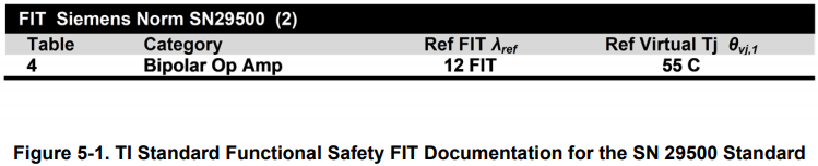
Various techniques exist for estimating BFR: experimental, derived from field observations of incidents and customer returns/field failures, or an estimation based on industry-accepted reliability guides coupled with some engineering judgement. 用于估计BFR的各种技术:实验技术,来自事故和客户回报/现场故障的现场观察,或基于行业接受的可靠性指南和一些工程判断的估计。 Here are a few examples of empirical techniques; however, these only account for intrinsic (silicon) failures and disregard the contribution from silicon and package interactions: 这里有几个经验技术的例子;然而,这些只解释了内在(硅)故障,而忽略了硅和封装相互作用的贡献: • Temperature bias operating life test • High-temperature operating life test • Extended life reliability test Field observations, on the other hand, require accurate and extensive record keeping, and this is not available when a new product is introduced to market. Additionally, many semiconductor manufacturers do not receive all of their customer returns, making it impossible to meet the requirement for accurate and extensive records to estimate BFR. 另一方面,实地观察需要准确和广泛的记录保存,当新产品被引入市场时,这是不可行的。 此外,许多半导体制造商没有收到他们所有的客户回报,因此无法满足准确和广泛的记录来估计bfr的要求。 The following industry reliability guides can provide a estimation for functional safety analysis: • IEC technical report (TR) 62380 and IEC 617095 • SN 29500, the Siemens AG standard for the reliability prediction of electronic and electromechanical components • FIDES such as a military handbook or other documentation from a credible source The remainder of this paper will focus on the use of IEC TR 62380 and SN 29500 to estimate BFR. 本文的其余部分将重点讨论使用IECTR62380和sn29500来估计BFR。 5 Siemens SN 29500 FIT modelSN 29500 uses a look-up table to find reference FIT rate and temperature for various component types such as: • Integrated circuits (ICs) • Discrete semiconductors • Passive components • Switches, relays, lamps, connectors, and so on The method for estimating the FIT rate of an IC starts by looking up a reference FIT rate value and reference die temperature value from tables. The tables are separated into three types: one table for integrated circuits, a second one for discrete semiconductors and a third one for passive components. These three tables are further divided into subcategories of IC/component type and then by a range of how many transistors are in the IC or discrete semiconductor component. 估计IC拟合速率的方法首先从表中查找参考拟合速率值和参考模具温度值。 这些表分为三种类型:一种用于集成电路,第二种用于离散半导体,第三种用于无源元件。 这三个表进一步分为IC/组件类型的子类别,然后按IC或离散半导体组件中有多少晶体管的范围划分。 In the excerpt shown in Figure 5-1, which is from a TI functional safety FIT document for a bipolar operational amplifier, the λ ref FIT rate is 12 FIT and the reference die temperature is 55°C. This information is sourced from the SN 29500 standard. 在图5-1所示的摘录中,它来自双极运算放大器的ti功能安全拟合文档,λ参考拟合率为12拟合,参考模具温度为55°c。 此信息来源于sn29500标准。
The SN 29500 standard includes calculations for adjusting the FIT rate from the reference condition to the FIT rate for the actual expected system operating conditions. Simply plug in the expected temperature profile and reference values into the equations, and calculate the component’s FIT rate in the context of the component’s use in the intended application. sn29500标准包括将拟合率从参考条件调整到实际预期系统运行条件的拟合率的计算。 只需将预期的温度剖面和参考值插入方程,并在预期应用程序中使用组件的上下文中计算组件的拟合率。 The following expresses the general equation for all types of components as: Application FIT rate = (1) reference FIT rate and temperature × (2)Temperature factors × (3)voltage factors × (4)current factors × (5)% time stress factors System integrators will need to refer to the information in the SN 29500 standard to derive their application’s specific FIT rate for a TI-supplied component. 系统集成商将需要参考sn29500标准中的信息,以导出其应用程序对ti提供组件的特定拟合率。 6 IEC TR 62380The IEC 62380 standard is also commonly used when estimating BFR in functional safety analysis. It is a reliability data handbook that outlines a universal model for predicting the reliability of electronic components, printed circuit boards (PCBs) and equipment. It was published in 2004, and subsequently obsoleted. However, the ISO 26262 standard (now in its second edition, revised in 2018) has incorporated the IEC 62380 standard as part of its newly published Part 11 – Guidelines on Application of ISO 26262 to Semiconductors. 在功能安全分析中,IEC62380标准在估计bfr时也是常用的。 这是一本可靠性数据手册,概述了预测电子元器件、印刷电路板(PCBs)和设备可靠性的通用模型。 它于2004年出版,随后被淘汰。 然而,ISO26262标准(现为其第二版,2018年修订)已将IEC62380标准纳入其新发布的第11部分-ISO26262在半导体中应用指南的一部分。 The IEC TR 62380 IC failure rate can be modeled as sum of the die, package and electrical overstress (EOS) related failure rates, where: • The die-related failure rate formula includes terms for IC type and IC technology, transistor count, thermal mission profile, junction temperature, and operating and non-operating lifetime. • The package-related failure rate formula includes terms for mechanical stress caused by thermal expansions, thermal cycles, thermal mission profile, package type and package materials. • The EOS failure rate formula includes terms for specific systems with an external interface and electrical environment Equation 1 shows the IEC TR 62380 BFR formula (reproduced from the original standard). System integrators will have to refer to the IEC 62380 standard to access the information required to calculate BFR.
Equation 2 expresses the die FIT according to IEC TR 62380 as:
• where N is the number transistor by type, λ 1 is the transistor type scale factor, λ 2 is the technology base fit rate and α is a factor for the current year of manufacture. Equation 3 expresses the package FIT according to IEC TR 62380:
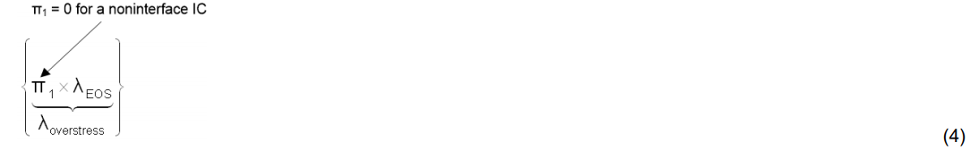
• where πα is the difference in thermal expansion coefficients of the IC vs. the PCB and λ 3 is the package scale factor by package type and size. Equation 4 expresses the EOS FIT according to IEC TR 62380:
• where the default assumption is that EOS = 0
If the IC application is listed in the table and the system has an external connection between the IC on the circuit board and the outside environment, then system integrators might add EOS values as needed. Table 6-1 is a screen image from a table for an automotive mission profile according to IEC TR 62380. According to this table, the overall working time for an automotive motor control application is approximately 500 hours per year with four day time starts, two night time starts, and 30-days a year of non-use.
• Choose only one technique and use that technique consistently. It could be: – Emperical (empirical) 以观察或实验为依据的 – Based on field data 基于现场数据 • State the model (Weibull or exponential) used for failure rate derived from field data 说明从现场数据导出的用于故障率的模型( Weibull或指数 ) – Based on reliability guide. (TI products use BFRs derived from reliability guides.) 基于可靠性指南。 ( TI产品使用来自可靠性指南的BFR ) • Assume a usage profile. Here are a couple of examples: 假设使用配置文件。 这里有几个例子: – Industrial: always on 24/7 year-round until a scheduled preventive maintenance cycle 工业:始终24/7全年,直到预定的预防性维护周期 – Automotive motor control: two to four starts per day, ~4 hours per day of use, as in IEC TR 62380 汽车电机控制:每天两到四次启动,每天使用4小时~,如IECTR62380 • Select (and state) the confidence interval (75%, 80%, 90%) for the underlying statistics used in the estimation 选择(和说明)估计中使用的基本统计量的置信区间( 75%、80%、90 %) • Clearly document any scaling factors or derates that have gone into the BFR estimation 清楚地记录任何已进入BFR估计的缩放比例因子或降级 • Account for non-operating time and solder-joint-based failures 解释非操作时间和基于焊点的故障 As long as all semiconductor suppliers use the same BFR estimation assumptions – or at minimum explicitly state their assumptions – it may be possible to compare the BFRs of comparable semiconductor components from two different manufacturers. 只要所有半导体供应商使用相同的Bfr估计假设-或至少明确说明其假设-就可能比较来自两个不同制造商的可比半导体元件的BFR。 8 Special Considerations for Transient FaultsSoft errors that result from a radiation event (internal or external) that could cause random hardware failures must be accounted for in a BFR estimate. However, soft errors caused by electromagnetic interference or crosstalk should not be included in BFR calculations because these are classified as systematic faults, which are manageable by adhering to good design practices. It is possible to modulate transient faults through attributes such as: 可能导致随机硬件故障的辐射事件(内部或外部)所产生的暂时性错误必须在BFR估计中解释。 然而,电磁干扰或串扰引起的软误差不应包括在BFR计算中,因为这些误差被归类为系统故障,通过坚持良好的设计实践,这些故障是可以管理的。 可以通过以下属性来调节瞬态故障: • The technology used • The impact of the fault and when applicable • Standard vs. low alpha vs. ultra-low alpha mold compounds in packages Architectural Vulnerability Factor (AVF) is the probability that a fault in a design structure, due to a soft error, will result in a visible error in the final output of the function. According to ISO 26262, the BFR for soft errors should not be de-rated based on AVF or safety mechanisms such as error detection and correction (EDAC) circuitry. Thus, it is best to calculate the BFR for soft errors separately for random access memory vs. logic blocks in semiconductor components. 架构漏洞因子(AVF)是设计结构中的故障由于软错误而导致函数最终输出可见错误的概率。 根据iso26262,不应基于AVF或安全机制(如错误检测和校正(EDAC)电路)对软错误的bfr进行降级。 因此,对于半导体元件中的随机存取存储器和逻辑块,最好分别计算软误差的BFR。 9 BFR Differences (Due to Package) Between IEC TR 62380 and SN 29500SN 29500 is deficient (vs. IEC TR 62380) in accounting for failures that are due to silicon and package interactions. Consequently, functional safety standards recommend that: SN29500在解释由于硅和封装相互作用而导致的故障方面存在缺陷(vs.IECTR62380)。 因此,功能安全标准建议: • Semiconductor component manufacturers estimate failures caused by silicon interaction with package materials and silicon-to-package connection points (pins) 半导体元件制造商估计硅与封装材料和硅到封装连接点(引脚)相互作用引起的故障) • System integrators account for failures attributable to the connection points between the semiconductor component and the boards (solder joints). These failures are typically analyzed at the element or system level. 系统集成商解释了由于半导体元件与板(焊点)之间的连接点而导致的故障)。 这些故障通常在元素或系统级别进行分析。 • ISO 26262 defines: – An element as a system, components (hardware or software), hardware parts, or software units; and 作为系统、组件(硬件或软件)、硬件部件或软件单元的元素;和 – A system as a set of components or subsystems that relates at least a sensor, a controller and an actuator with one another. 系统作为一组组件或子系统,至少与传感器、控制器和执行器相互关联。 IEC TR 62380 accounts for both the interaction between silicon die and the lead frame/substrate and the connection between solder joints. In contrast, the package failure rate in SN 29500 only considers die-topackage interactions, which leads to inherent optimism in BFR estimations when using SN 29500. IECTR62380解释了硅模与引线框架 / 基板之间的相互作用以及焊点之间的连接。 相反,sn29500中的包故障率只考虑模顶相互作用,这导致了使用sn29500时bfr估计中固有的乐观。 10 Effect of Power-on Hours on BFRISO 26262 recommends applying these attributes to minimize the scaling or unjustifiable reduction of the calculated BFR: • An accurate mission profile • Assessing the applicability of failure modes in the operating conditions (as specified in the mission profile) • Determining the fail rate per unit (on the per-hour, day, month or year for which the system will be operated) The BFR formula in IEC TR 62380 accounts for τON and τOFF, whereas SN 29500 accounts for τW. 11 What Can You Expect for TI Products TI has three categories of functional safety products: Functional Safety-Compliant, Functional Safety QualityManaged and Functional Safety-Capable. More information on TI's functional safety products are available here. All TI functional safety products promoted for applicability in functionally safe systems come with functional safety FIT rate and failure mode distribution (FMD). For our most complex products like microprocessors, microcontrollers and analog signal-chain products, system integrators will get a comprehensive failure modes, effects and diagnostics analysis (FMEDA) that is inclusive of the FMD based on a BFR estimated according to IEC TR 62380. For our least complex analog products, like low dropout oscillators, operational amplifiers and voltage supervisors, system integrators receive a functional safety FIT, pin failure mode analysis and a FMD report that adhere to a standard TI-wide format.
Links to example reports that outline this information follow: • Texas Instruments, Functional Safety FIT Rate, Failure Mode Distribution TPS7A16A-Q1 • Texas Instruments, Functional Safety FIT Rate, Failure Mode Distribution TPS3851-Q1 12 Summary System integrators can create safer, reliable designs faster with products, engineering expertise, and design resources from TI. Additionally, system integrators can meet the rigorous requirements of functional safety standards, such as ISO 26262 and IEC 61508, by choosing products that come with a BFR based on either IEC TR 62380 or SN 29500. 13 References1. IEC 61508: Second edition 2010-04: Functional safety of electrical/electronic/programmable electronic safety – related systems. 2. ISO 26262: Second Edition 2018-12: Road Vehicles – Functional Safety, ISO 26262, International Organization for Standardization (2018) 3. IEC/TR 62380:2004(E): Reliability data handbook – Universal model for reliability prediction of electronics components, PCBs and equipment 4. SN 29500: Siemens Norm SN 29500/ Edition 2010-09 5. IEC 61709: Third Edition 2017-02: Electric components – Reliability – Reference conditions for failure rates and stress models for conversion Functional Safety FIT Rate, Failure Mode Distribution TPS7A16A-Q1https://www.ti.com/lit/pdf/slvael4?keyMatch=FUNCTIONAL%20SAFETY%20FIT%20RATE%20FAILURE%20MODE%20DISTRIBUTION%20TPS7A16A-Q1&tisearch=Search-EN-everything 60-V, 5-μA IQ, 100-mA, low-dropout voltage regulator with enable and power-good
(1)Failure Rate, Mission Profile and Failure Modes Distribution The failure rate and mission profile information comes from the Reliability data handbook IEC TR 62380 using the reliability modeling for Integrated circuits with automotive motor control mission profiles Power dissipation 475mW Climate type: World-wide Table 8 Package factor lambda 3 Table 17b Substrate Material: FR4 EOS FIT rate assumed = 0 The failure mode distribution estimation comes from the combination of common failure modes listed in standards such as IEC 61508 and ISO 26262, the ratio of sub-circuit function size and complexity and from best engineering judgment. The failure rates listed reflect random failure events and do not include failures due to misuse or over stress. The TPS7A16A-Q1 is a catalog product and not compliant to ISO-26262 standards. Functional Safety FIT Rate, Failure Mode Distribution TPS3851-Q1https://www.ti.com/lit/fs/sbva075/sbva075.pdf?ts=1605150824966&ref_url=https%253A%252F%252Fwww.ti.com%252Fsitesearch%252Fdocs%252Funiversalsearch.tsp%253FsearchTerm%253D%2BFunctional%2BSafety%2BFIT%2BRate%252C%2BFailure%2BMode%2BDistribution%2BTPS3851-Q1 High-Accuracy Voltage Supervisor with Integrated Watchdog Timer
(1) Failure Rate, Mission Profile and Failure Modes Distribution The failure rate and mission profile information come from reliability modeling for Integrated circuits in Reliability data handbook IEC TR 62380 and ISO 26262 Part 11 Mission Profile: Motor Control from Table 11 Power dissipation 1.0 mW Climate type: World-wide Table 8 Package factor lambda 3 Table 17b Substrate Material: FR4 EOS FIT rate assumed = 0 (2) Reference failure rate, Virtual (equivalent) junction temperature The reference failure rate and virtual junction temperature come from Siemens Norm SN29500-2 tables 1-5. Failure rate for user mission profile is calculated using the reference failure rate and virtual junction temperature and following the calculation information in SN29500-2 section 4. The failure mode distribution estimation comes from the combination of common failure modes listed in standards such as IEC 61508 and ISO 26262, the ratio of sub-circuit function size and complexity and from best engineering judgment. The failure rates listed reflect random failure events and do not include failures due to misuse or over stress. TPS3851-Q1 is a catalog product and not compliant to ISO-26262 standards. Streamline your functional safety system certification https://www.ti.com/technologies/functional-safety/overview.html
|


【本文地址】